Overview
The National Association of Rocketry (NAR) has developed a certification process divided into 3 levels. Depending on your level of certification, greater impulse solid fuel motors become available to purchase and launch commercially. In order for AerospaceNU to continue working at its current scale it is essential that someone on the team be certified up to at least the L2 level, enabling the use of up to L class motors.
To attain a L2 cert, the individual must first complete the L1 process of entirely self designing, building, and launching a rocket successfully on an I, J, or K class motor. They must then take a written exam to demonstrate their knowledge of regulations and laws pertaining to high power rocketry. Finally they must successfully fly and recover a self built rocket on a L, M or N class motor.
Approach
To save both time and money I decided to design a rocket capable of flying safely on both the maximum allowed L1 motor and the minimum required L2 motor without any changes to the body. I started this process by creating a cross sectional model of the rocket to get a rough idea of layout, an approximation of the rocket's center of gravity and center of pressure, and necessary thrust loading.
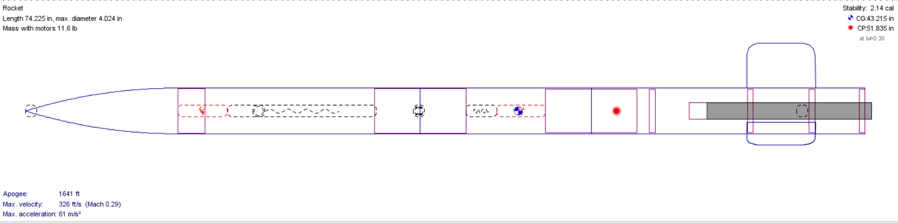
The airframe was designed with an extra long upper parachute bay to accommodate potentially implementing a payload. At the time of this design I was also preparing to teach an introduction to rocketry course, which would incorporate payloads, so I intended to design this rocket as a test bed for the payload deployment interface that would be used in that course.
Following this blueprint I purchased materials and began assembly of the known finalized sections including the parachute bays and electronics bay. The electronics bay was composed of two parallel wooden sleds secured by SLS printed Nylon 12 bulkheads that incorporated slits for the sleds to be inserted into and cylindrical protrusions to fill with black powder for separation charges. These sleds served as the mounting surface for the altimeters, barometers, and accelerometers used to control flight event timing. The bulkheads were clamped around a section of fiberglass coupler using threaded rods that ran the length of the electronics bay.
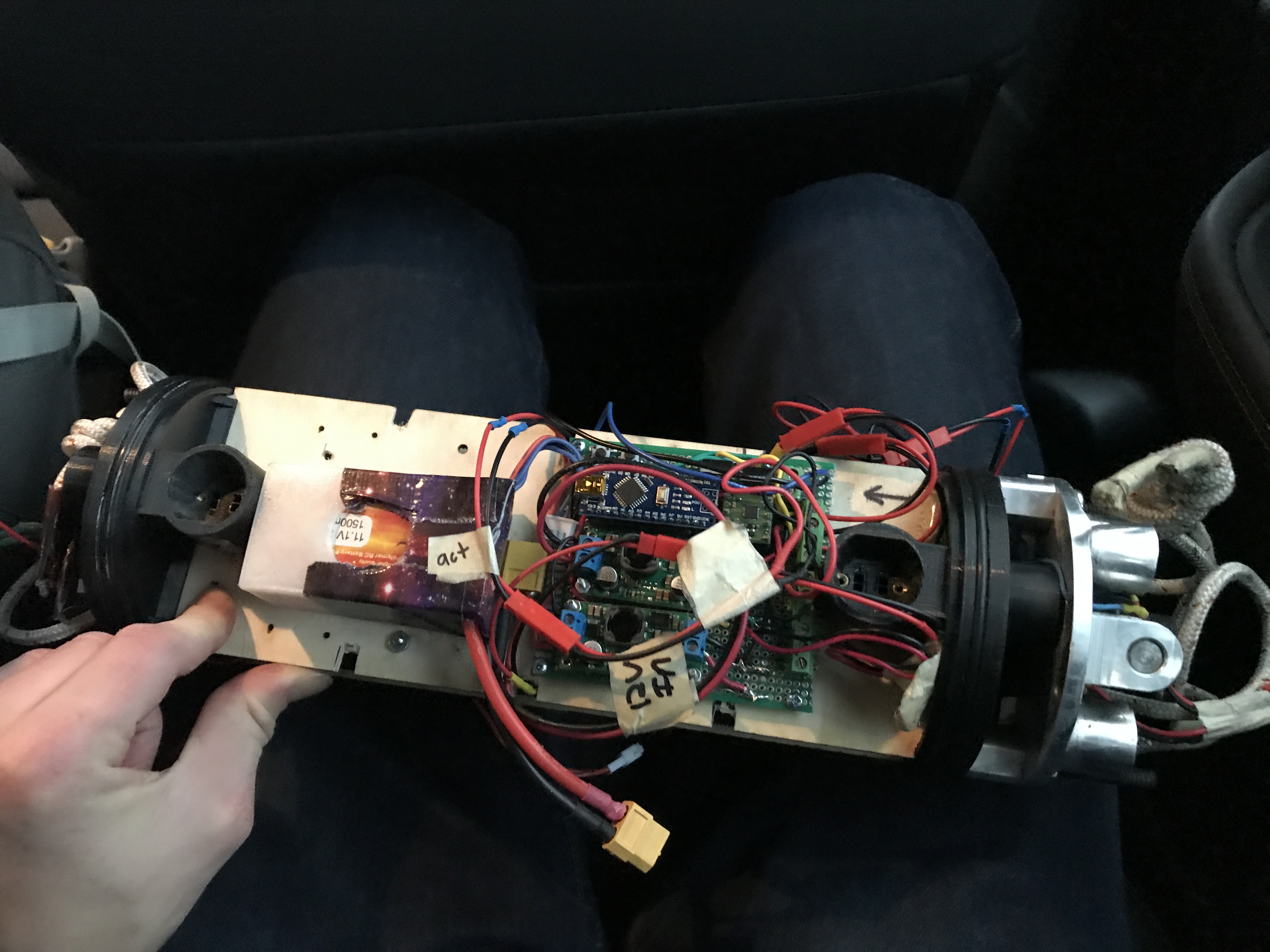
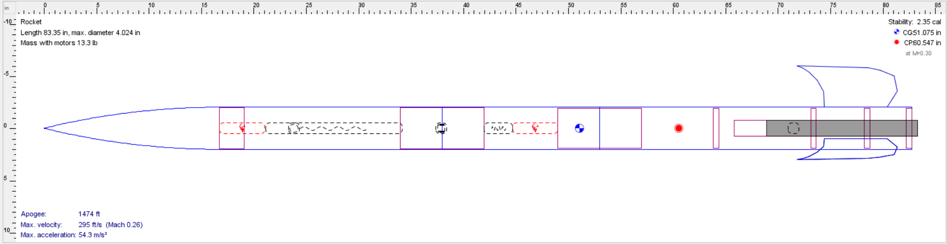
Since my certification flight would not be incorporating a payload I had to shorten the upper bay temporarily in order for it to be pressurized enough to separate at parachute deployment. To do this I floated a wooden bulkhead on the protruding threaded rods as shown in the picture above. Once the rocket was assembled for all components but the fins I found the actual mass and CG of the rocket and updated my 2D sim to account for this. This allowed me to decide on a final fin shape that produced a stable CAL off the rail.
This final fin design was then SLS printed out of Nylon 12 and the removable fin motor section was assembled. The fins were designed to be removable to accommodate large changes to the rocket's CG due to the variance of its future payloads. Fin design flexibility allows for the center of pressure of the rocket to remain easily modifiable, enabling a greater range of potential payloads.
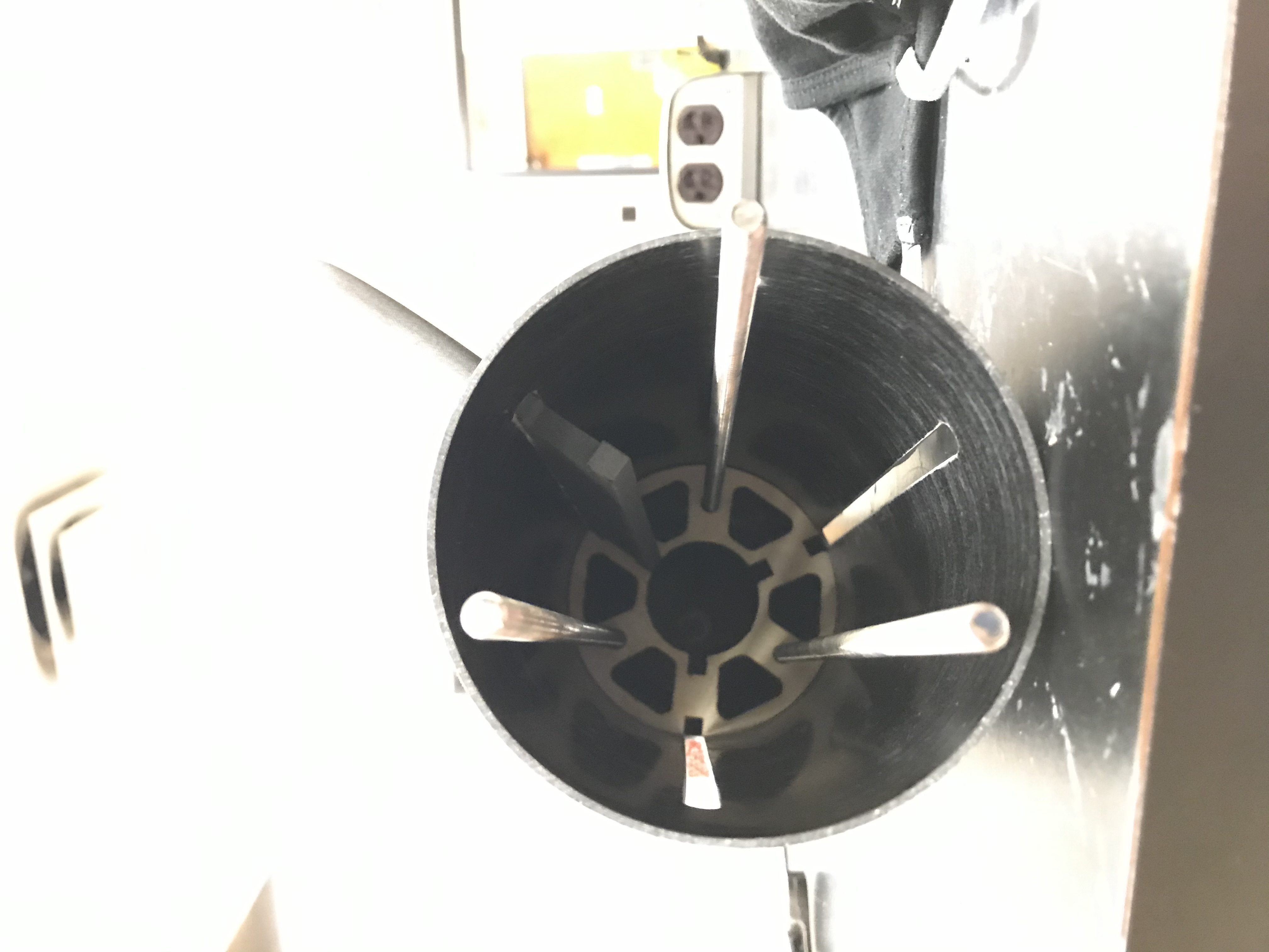
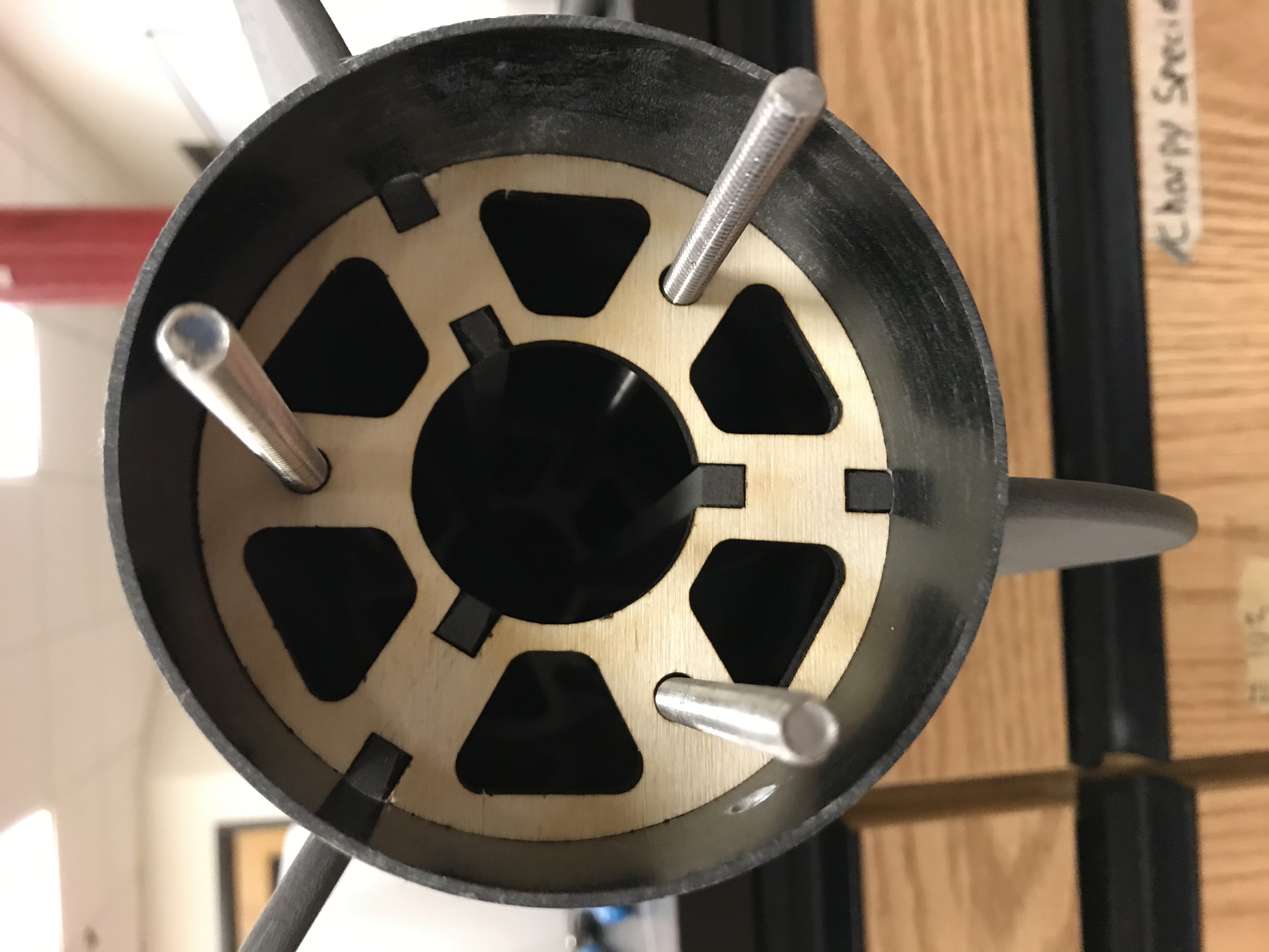
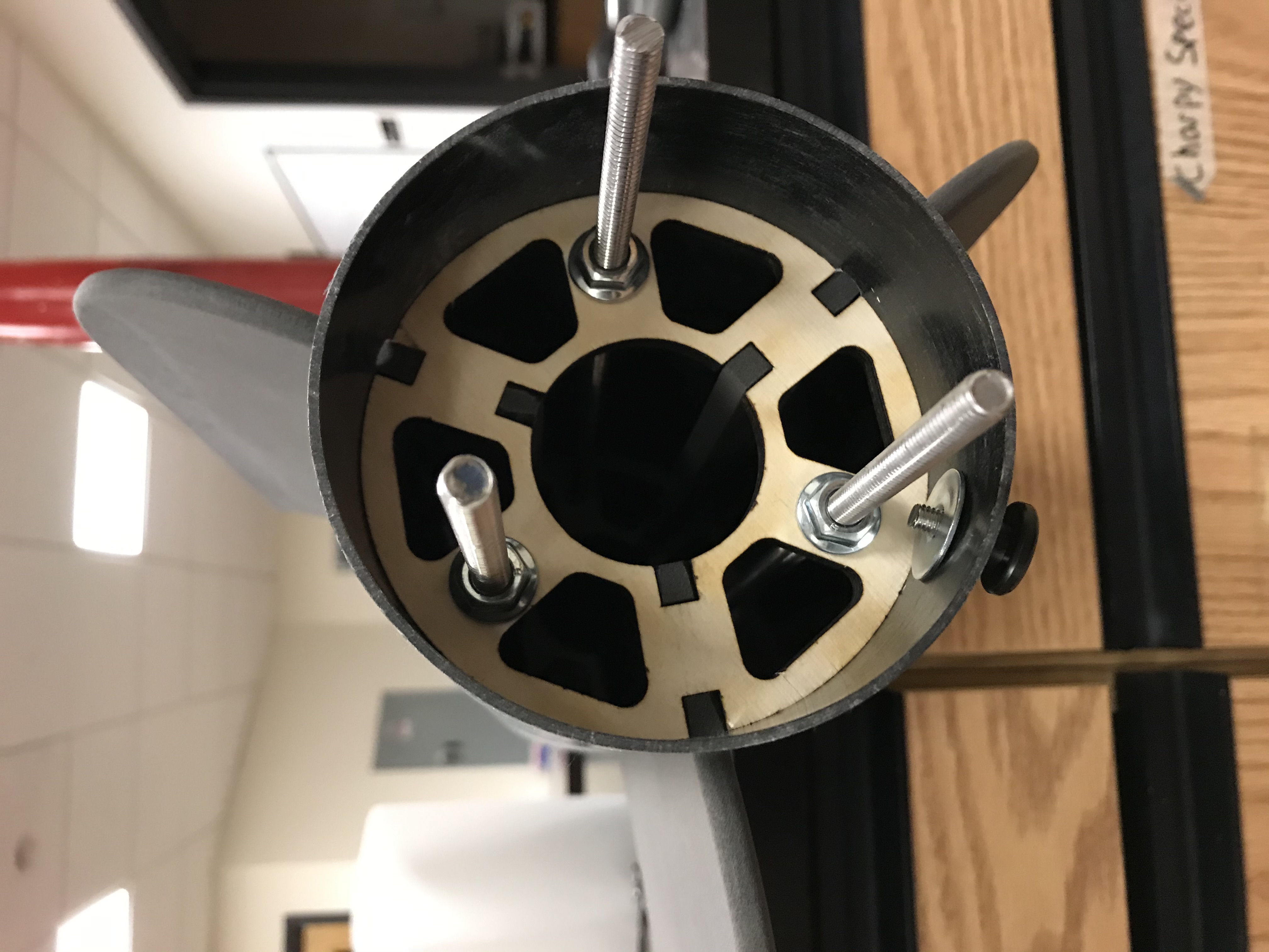
Fig 4. Fin can assembly showing a single fin slotted in its centering ring (left) and the completed assembly of all 3 fins sandwiched between two centering rings (right)
The retention system of this removable fin assembly (shown above) involved the addition of tabs onto either end of the inner spine of the fins. These tabs would then be inserted into receiving cutouts on the two centering rings. These centering rings were laser cut out of 1/4" thick pine wood. The rings were compressed against the fin spines using the threaded rod that ran the length of the motor section. Nuts were attached on either end of the assembly and tightened down until adequate compression was achieved.
Once the rocket was in a final state of assembly I ran ejection tests on the ground to verify that my estimated charges could actually induce a separation.
The first ejection test highlighted an issue with the rocket's construction. The upper bulkhead of the motor section was reinforced in preparation for the shock it would experience on parachute deployment. The threaded rods secured with nuts and epoxy fillet around the edge of the bulkhead both provided plenty of structural support for axial forces directed from the rocket tail to its tip. I failed to account for the axial force directed from rocket tip to its tail, created during chamber compression at separation. This resulted in the bulkhead being pushed down the tube of the rocket, along with its threaded rods, which could then no longer retain the motor. This failure, created while ejection testing, is shown below.
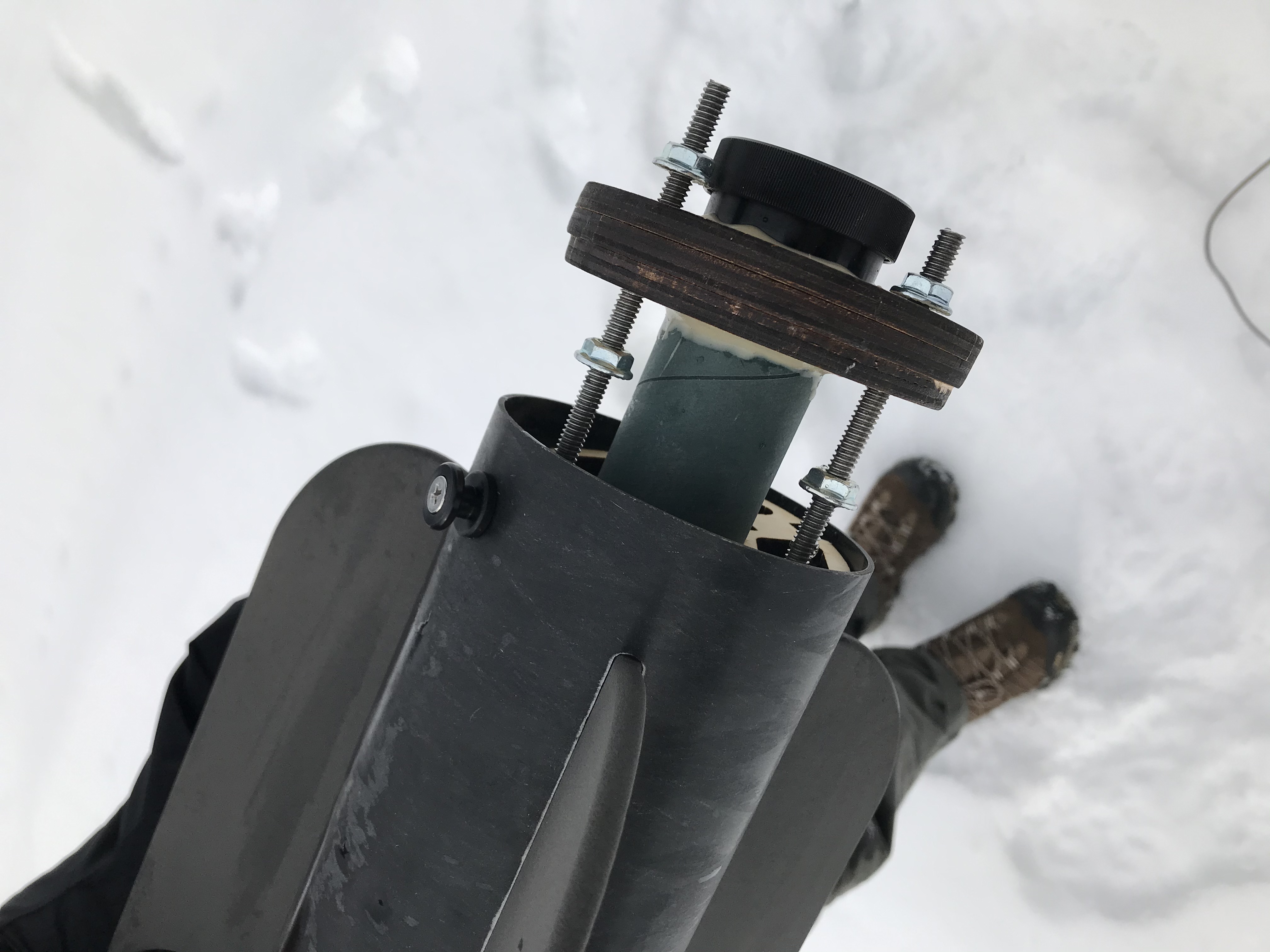
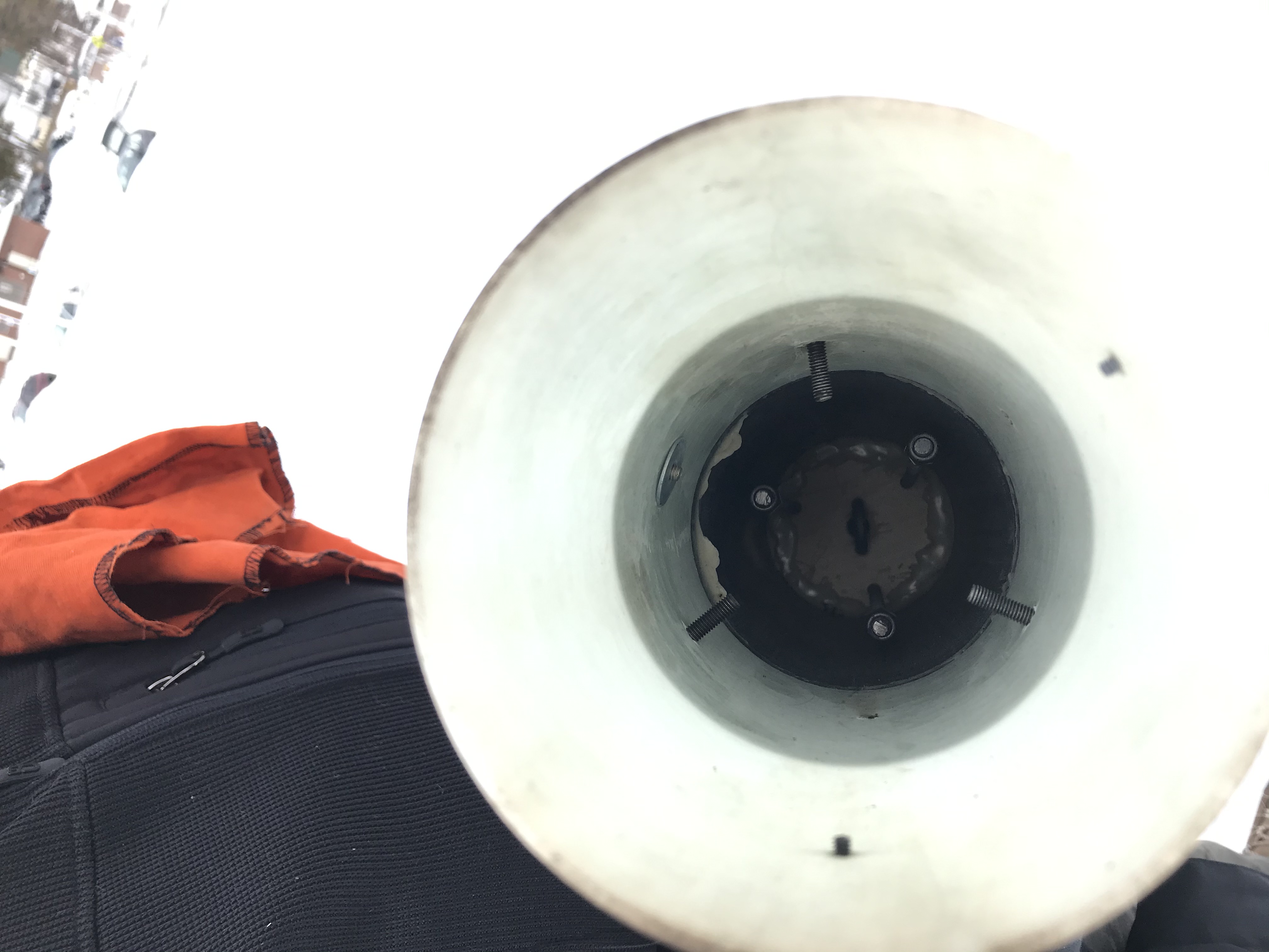
Fig 5. First ejection test failure
In response to this, rather than relying on epoxy to fix the bulkhead to the airframe, a small section of coupler tube was attached just below the bulkhead to act as a hard-stop. The bulkhead was then clamped down against that hard-stop shelf using the threaded rods that run the length of the motor section.
This change was then once again validated through the successful ejection test shown below.
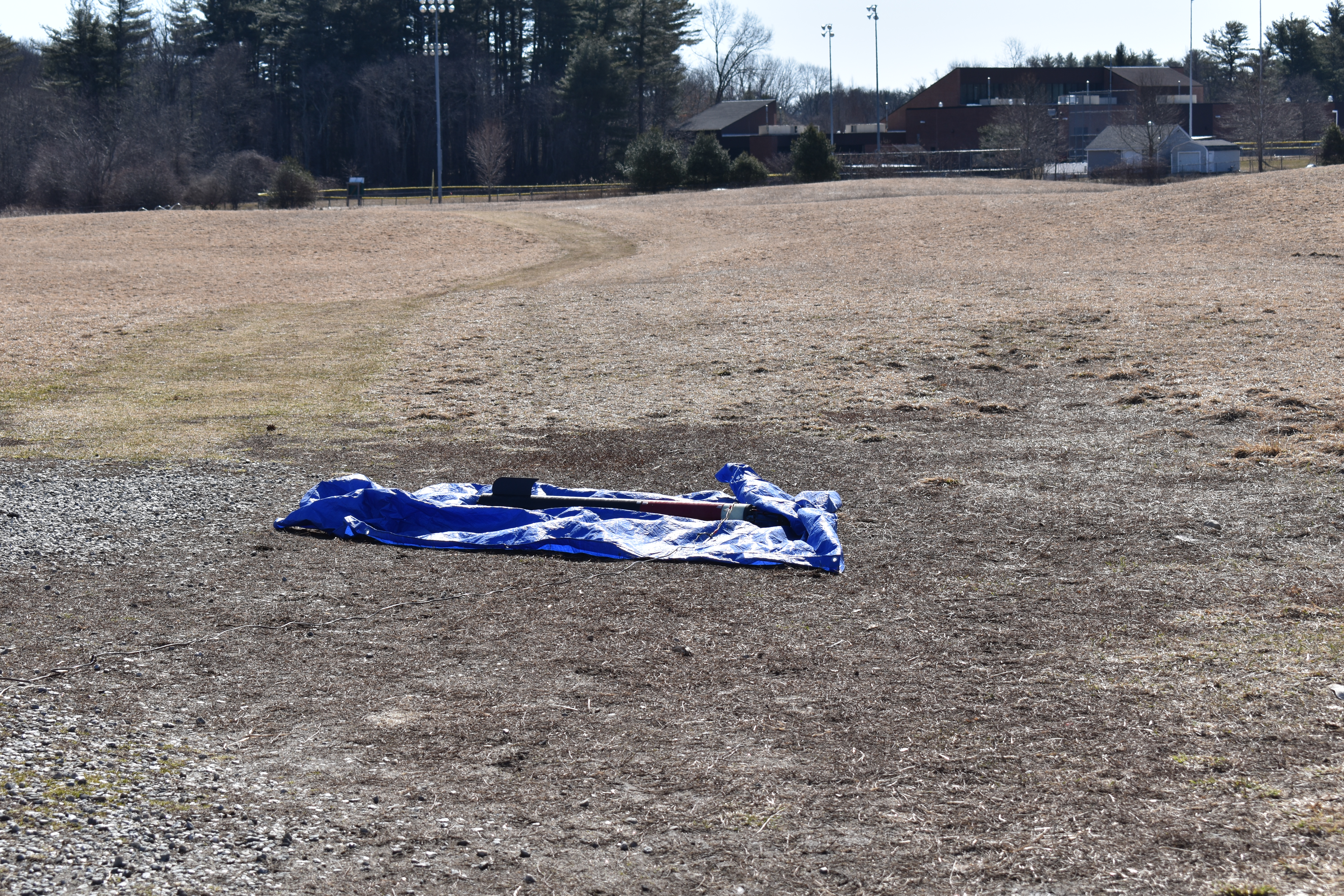
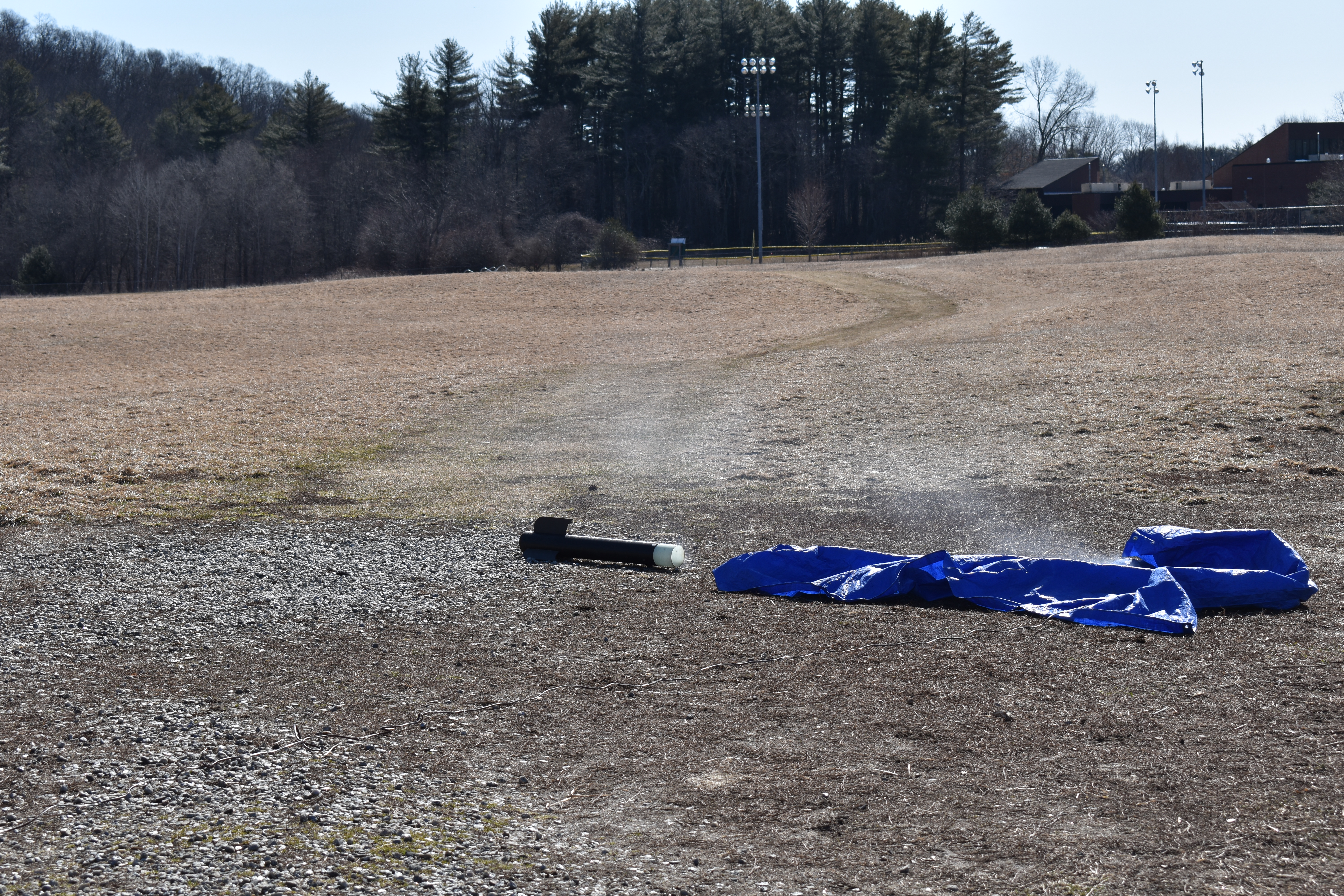
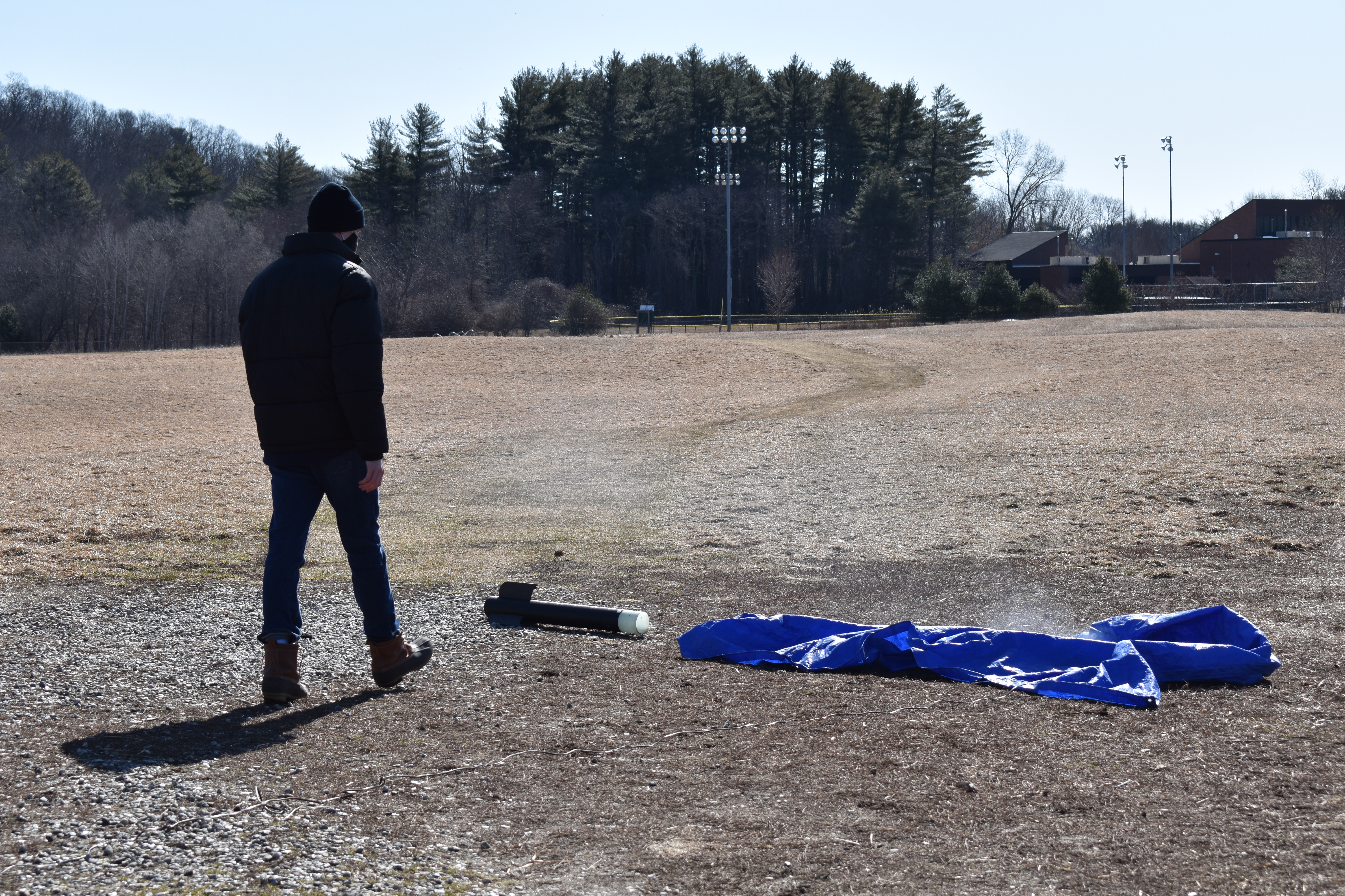
Fig 6. Frame by frame of the parachute ejection test for the lower parachute bay
Both L1 and L2 flights were successful for this rocket but had a few important takeaways for future designs. Although my rocket had a stable average CAL of 2.5 the CAL off the rail was around 1.6 and there was visually a bit of wobble in its takeoff. This was resolved during my L2 flight thanks to the greater acceleration of the rocket due to the larger motor. During the building process my rocket quickly accumulated more weight than I had originally projected which is part of what led to the low off the rail CAL for the L1 flight. I will have to more conscious of weight budget in future builds.